
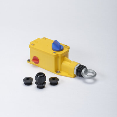
PAS
Article Number: 91.057 560.xxx
- Single-side Installation up to 75m*
- Plastic-Enclosure
- Reset knob
Features
Kiepe pull-rope emergency stop switches type PAS are used in accordance with the requirements of EN 620 as well as BGI 710 and in conformity with DIN EN ISO 13850 as emergency stop devices as supplementary safety measures on conveyor belt systems and finishing and processing machines. The pull rope is tensioned on one side of the actuating shaft. With the KIEPE pull-rope-system functionally aligned, the emergency stop signal can be triggered over a distance of 30 m with a maximum temperature variation of +/-20°C in the application. Less temperature variation allows a longer installation length f.ex. for applications in production halls. Kiepe pull rope emergency stop switches type PAS comply with Machinery Directive 2006/42/EG. The device must only be used in electrical control circuits.
The PAS plastic housing is equipped with 1 SPDT and 1 N.C. contact (positive opening). Taking into consideration the safety data and maintenance recommendations, the pull rope emergency stop switch type PAS can be used in safety circuits in accordance with DIN EN ISO 13849 up to Performance Level d (PLd).
Corrosive
- Powder
- Suitable
- Gravel
- Not Suitable
- Rubble
- Not Suitable
Non-Corrosive
- Powder
- Suitable
- Gravel
- Not Suitable
- Rubble
- Not Suitable
The emergency stop signal can be activated by pulling or breaking of the pull wire or by pushing the blue emergency stop button when the switch is correctly adjusted. The spacer tool* helps to find the correct operating position for a proper work and has to be removed after adjustment. The microswitches are actuated by a spring supported cam disc at the same time. The emergency stop signal is performed with positive-making normally closed (NC) contacts in accordance with the closed circuit principle. After the emergency stop function is triggered, the switching mechanism is locked in the shut-off position “0“. The blue reset button can only be removed to position “1“, when the actuating shaft is back in operating position. In position “1“, the switching contacts are reactivated and the conveyor belt is prepared for start up the belt conveyor.
Note Resetting the pull rope emergency stop switch must not cause in starting up the conveyor system.
| Designation | Pull rope emergency stop switch type PAS emergency stop device with latching function |
|---|---|
| Type of actuation | Pull rope - single-side installation, integrated wire-break detection |
| Complies with | DIN EN 60947-5-5; IEC 60947-5-5 |
| Suited for | Control circuits in accordance with DIN EN 60204 -1 |
| Pull rope length (with external spring) | 1x 30 m bei 40 Kelvin 1x 50 m bei 25 Kelvin 1x 75 m bei 17 Kelvin |
| Enclosure | Thermoplastic, yellow, similar to RAL 1004 |
|---|---|
| Reset button | PARA, blue, similar to RAL 5010 |
| Fixation | 4 x M6 |
| Net Weight (typic) | 0.4 kg |
| Switching system | Positive-opening snap-action switches; according DIN EN 60947-5-1; cam operated |
|---|---|
| Cable entries | 3x M20 x 1.5 threaded holes with 1x cable gland (sealing Ø 6 mm ...Ø 12 mm) 2x Dummy screw |
| Utilization category Ue/Ie | AC-15: 230 V / 1.5 A DC-13: 24 V / 2.0 A |
| Connection cross section (max.) | 2.5 mm2 |
| Protective conductor connection | Protection class II / Protective Insulation |
| Rated insulation voltage Ui | 250 V |
| Rated impulse withstand voltage Uimp | 2.5 kV, Degree of Pollution III |
| Conventional thermal current Ith | 6 A |
| Ambient Temperature | -25°C.. + 70°C |
|---|---|
| Enclosure Protection Rating (EN 60529) | IP65 |
| Electrical reliability | @ DC-13: 24 V / 2 A @ AC-15: 230 V / 1.5 A | B10d = 200.000 cycles B10d = 840.000 cylces |
|---|---|---|
| Mechanical reliability | 840.000 cycles | |
Safety classification (depending upon system architecture / Variants with minimum 2 Normally closed contacts) | DIN EN ISO 13849-1 DIN EN 62061 | up to PLd up to SIL 2 |
Pull-rope emergency stop switches of type PAS are fastened to the substructure in the installation position using 4 M6 screws each. The electrical connection is made when the device is open via the cable gland included in the scope of delivery to the connection terminals of a circuit board. The pull rope is tensioned with the tension spring between the anchor hook and the mounting ring of the switch until the spacer can be easily removed from the switch. This is the operating point. The switch can only be reset at the operating point. The spacer must be removed and the bellow be attached to the housing.
Note The tension springs are designed for cable systems with Kiepe devices at the recommended temperature changes in a straight installation.


Variants
| Name | Ordering No. | Weight | Contacts NC NO SPDT |
|---|---|---|---|
| PAS 001 | 91.057 560.001 | 0.5 kg / 1 Unit | 1 1 |
| PAS 101 Metall parts Stainless, Plastic bearing | 91. 057 650.101 | 0.5 kg / 1 Unit | 1 1 |
Downloads
You have a question? We are here for you!
We are looking forward to hearing from you. We are happy to advise you and help you with the selection of the right product.