
PRS
Article Number: 91.063 293.xxx
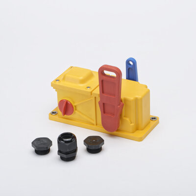
- Installation Double-side
- Plastic-housing
- Reset lever
Features
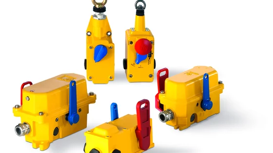
Kiepe pull-rope emergency stop switches type PRS are used as emergency stop devices as supplementary safety measures on fixed belt conveyors. The pull rope is symmetrically tensioned on both sides of the red release lever. The exclusive use of glass fiber reinforced plastic and stainless steel is designed especially for applications in harsh environments such as potassium salt and rock salt factories, seaports and urea, recycling and composting facilities. With the pull-rope system functionally aligned, the emergency stop signal can be triggered over a distance of up to 100 m for each switch. Kiepe pull-rope emergency stop switch types PRS comply with Machinery Directive 2006/42/EC. They must only be used in control electrical circuits. The PRS glas fiber reinforeced plastic housing offers space for 2 NC and 1 changeover contact. The versions PRS 101/102 use also a NO contact for a signal lamp. Only one contact of each changeover contact must be used for auxiliary circuit switches. Taking into consideration the safety data and maintenance recommendations, the pull-rope emergency stop switch type PRS can be used in safety circuits in accordance with DIN EN IS0 13849 up to Performance Level d (PL d).
Corrosive
- Powder
- Suitable
- Gravel
- Suitable
- Rubble
- Not Suitable
Non-Corrosive
- Powder
- Suitable
- Gravel
- Suitable
- Rubble
- Not Suitable
The pull-rope emergency stop switch is actuated by a pull rope 1 connected on both sides of the red release lever. The switching of the pull rope switch is controlled by a cam and supported by a spring function (snap action). The self-cleaning contacts are actuated simultaneously and it may be carried out a cross comparison of the contacts of an external control unit. The emergency stop signal is performed with positive-making normally closed (NC) contacts in accordance with the closed circuit principle. After the emergency stop function is triggered, the switching mechanism is locked in the shut-off position “0”. The signal lamp in the lid of PRS 101 or 102 is switched on. When the blue reset lever is actuated in switch position “1”, the switching contacts are reactivated, the signal lamp is off and the conveyor belt is prepared for being turned back on again.
Note Resetting the pull rope emergency stop switch must not cause in start up the conveyor system.
| Designation | Pull-rope emergency stop switch type PRS – emergency stop device with latching function |
|---|---|
| Type of actuation | Bidirectional (double-side) |
| Complies with | DIN EN 60947-5-5; IEC 60947-5-5 |
| Suited for | Control circuits in accordance with DIN EN 60204 -1 |
| Pull-rope length, approved | 2 x 50 m (typically) |
| Material | Enclosure : Thermoplastic resin, yellow (similar RAL 1004) release lever: red (similar RAL 3000) reset lever: blue (similar RAL 5010) |
|---|---|
| Mounting | 2 x M6 |
| Actuation force | 20 N ± 5 N |
| Net weight (typic) | 480 g |
| Switching system | „Snap action“ micro switches (SPDT), positive opening according to IEC 60947-5-1 |
|---|---|
| Cable entry | Threaded holes 3x M25 x 1.5 with each dummy screws, 1x cable gland enclosed (sealing area ∅ 9 mm to ∅ 17 mm) |
| Utilization category | AC-15: 230 V / 1,5 A DC-13: 24 V / 2 A |
| Connection cross section (max.) | 2,5 mm2 |
| Protective conductor connection | Protection class II, Protective insulation |
| Rated insulation voltage Ui | 250 V |
| Rated impulse withstand voltage Uimp | 2.5 kV, degree of pollution 3 |
| Conventional thermal current Ith | 6 A |
| Signal lamp | LED in the lid |
| Voltage Ub for signal lamp | PRS 101: 230 V AC PRS 102: 24 V DC |
| Current consumption of lamp | 20 mA |
| Permissible ambient temperature | - 25 °C ... + 70 °C |
|---|---|
| Protection rating (EN 60529) | IP67 |
| Electrical reliability | DC-13: 24 V / 2 A AC-15: 230 V / 1,5 A | B10d = 200.000 cycles B10d = 840.000 cycles |
|---|---|---|
| Safety classification Depending upon system architecture | DIN EN ISO 13849-1 DIN EN 62061 | Up to PL d Up to SIL 2 |
| Mechanical reliability | 200.000 cycles |
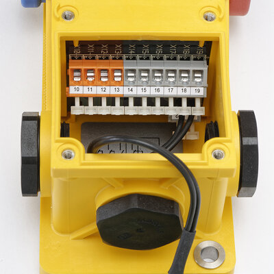
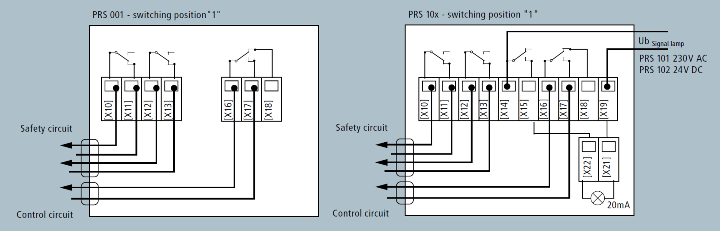
Pull-rope emergency stop switches of types PRS are centered between the anchor hooks [3] of the pull-rope system and each fastened to the substructure in installation position with 2x M6 screws. Electrical connection is performed with the device open using the screwed cable gland included in the delivery, directly on the terminal block [X10] to [X22] (see the connection drawings). The signal lamp of DC-Variant PRS 102 can be connected without regarding the polarity of the voltage. The pull-rope [1] is tensioned by tension springs [2] between the anchor hooks [3] and fastened onto the red release lever. After the tension springs [2] have been adjusted, the actuation force and path for triggering the switch must be tested to ensure compliance with specified requirements.
Note The Kiepe tension springs are designed for pull rope systems with Kiepe devices at recommended temperature changes in a straight installation. Deviations from that may need other spring design or adjusted tensioning for wire break detecion.


Variants
| Name | Ordering No. | Weight | Contacts NC NO SPDT | Actuating Lever | Signal Light LED |
|---|---|---|---|---|---|
| PRS 001 | 91.063.293.001 | 0.6 kg / 1 Unit | 2 1 | ||
| PRS 101 | 91.063.293.101 | 0.5 kg / 1 Unit | 2 1 | AC 230 V | |
| PRS 102 | 91.063.293.102 | 0.5 kg / 1 Unit | 2 1 | DC 24 V |
Downloads
You have a question? We are here for you!
We are looking forward to hearing from you. We are happy to advise you and help you with the selection of the right product.