
SEG
Article Number: 91.056 400.xxx
- Installation Double-side
- Cast-iron-housing
- Reset lever
Features
Kiepe pull-rope emergency stop switches type SEG are used in accordance with the requirements of EN 620 as well as BGI 710 and in conformity with DIN EN ISO 13850 as emergency stop devices as supplementary safety measures on conveyor belt systems. The pull rope is symmetrically tensioned on both sides of the red release lever. The devices are suitable for outdoor use and applications where the ambient temperature varies considerably. With the pull-rope system functionally aligned, the emergency stop signal can be triggered over a distance of up to 2 x 125 m for each switch. Kiepe pull-rope emergency stop switch type SEG comply with Machinery Directive 2006/42/EC and UKCA conformity is available. They must only be used in control electrical circuits. The SEG aluminium housing offers space for up to 3 simultaneously switching NO and NC contacts. Taking into consideration the safety data and maintenance recommendations, the pullrope emergency stop switch type SEG can be used in safety circuits in accordance with DIN EN ISO 13849 up to Performance Level d (PLd)
Corrosive
- Powder
- Conditionally Suitable
- Gravel
- Suitable
- Rubble
- Suitable
Non-Corrosive
- Powder
- Suitable
- Gravel
- Suitable
- Rubble
- Suitable
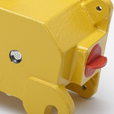
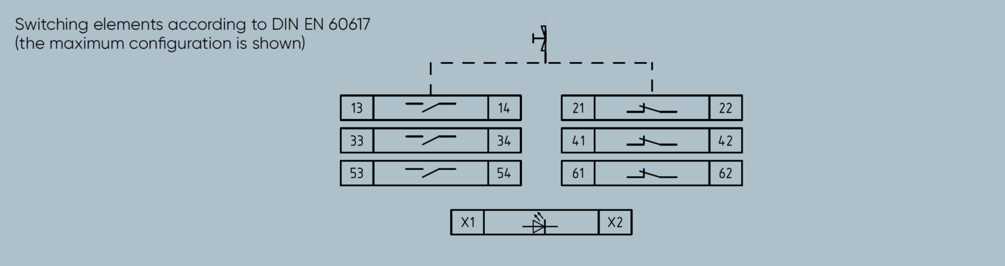
The pull-rope emergency stop switch is actuated by a pull rope 1 connected on both sides of the red release lever. The contacts are actuated by a spring supported cam disc (snap action function). At the same time, up to three NC and NO contacts are actuated simultaneously and a cross comparison of the contacts can be performed with an external control unit. The emergency stop signal is performed with positive-making normally closed (NC) contacts in accordance with the closed circuit principle. After the emergency stop function is triggered, the switching mechanism is locked in the shut-off position "0". When the blue reset lever is actuated in switch position "1", the switching contacts are reactivated and the conveyor belt is prepared for being turned back on again.
Note Resetting the pull-rope emergency stop switch must not cause the conveyor system to start up.
| Designation | Pull-rope emergency stop switch type SEG– emergency stop device with latching function |
|---|---|
| Type of actuation | Bidirectional (double-side) |
| Complies with | DIN EN 60947-5-5; IEC 60947 -5-5 |
| Suited for | Control circuits in accordance with DIN EN 60204-1 |
| Enclosure | Cast iron |
|---|---|
| Finish | PU 2K -paint Enclosure – yellow (RAL 1004), release lever – red (RAL 3000), reset lever – blue (RAL 5010) |
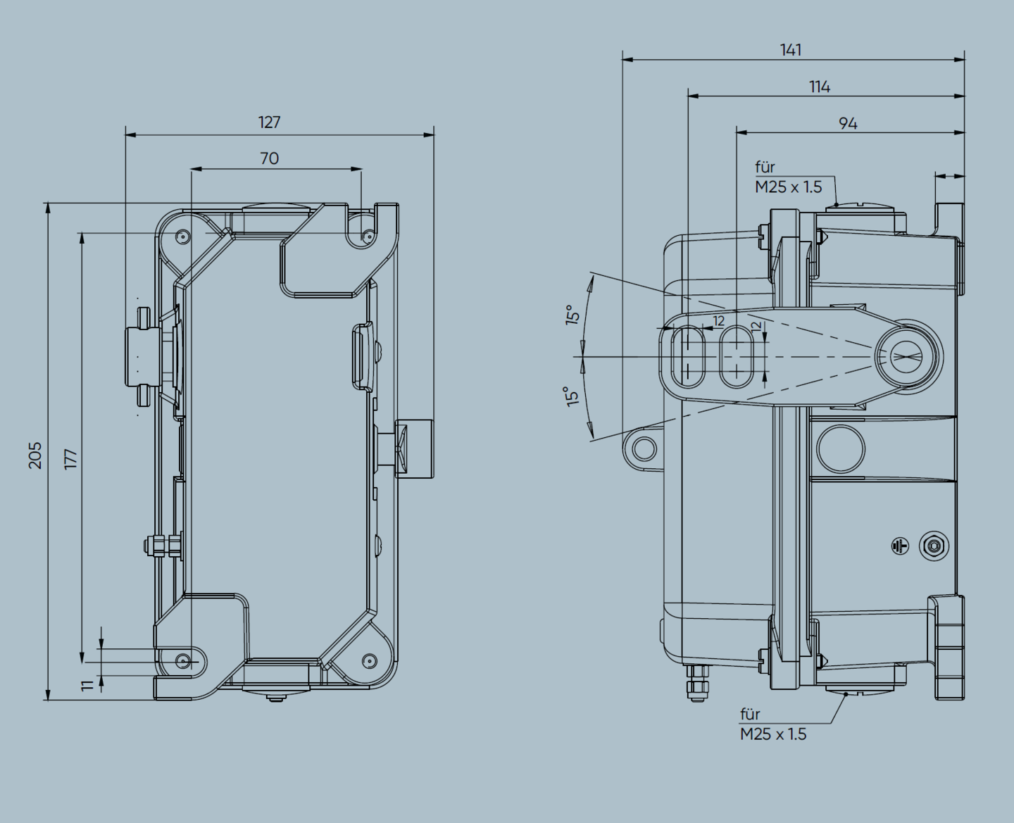
| Mounting | 2 x M10 |
| Pull-rope length (approved, max.) | 2 x 125 m (dependent from design of external tension springs and max. temperature change) |
| Actuation force | 30 N ± 10 N |
| Weight | 4.9 kg |
| Switching system | Up to 3 NC and NO contacts; cam operated positve-opening switches (EN 60947-5-1) |
|---|---|
Cable entry (included in scope of supply) | 2 x M25 x 1,5, with red transport lock (1x screwed cable gland: sealing area Ø 11 mm to Ø 16 mm; 1x dummy screw) |
| Utilization category | AC-15: 230 V / 6 A DC-13: 125 V / 0,8 A DC-13: 24 V / 2 A |
| Connection cross section (max.) | 2.5 mm2 |
| Protective conductor connection | Protection class I / Protective earthing |
| Rated insulation voltage Ui | 400 V |
| Rated impulse withstand voltage Uimp | 2.5 kV, degree of pollution 3 |
| Conventional thermal current Ith | 16 A |
| Permissible ambient temperature | –25 °C …+70 °C |
|---|---|
| Protection rating (EN 60529) | IP66 / IP67 |
| Safety classification Depending upon system architecture | DIN EN ISO 13849 -1 (up to PLd) DIN EN 62061 (up to SIL 2) | |
|---|---|---|
| Electrical Reliability | DC-13: 24 V / 2 A AC-15: 230 V / 6 A | B10d > 25.000 cycles B10d > 25.000 cycles |
Pull-rope emergency stop switches of type SEG are each fastened to the substructure in installation position with 2 M10 screws, centered between the anchor hook [3] of the pull-rope system (see the mounting diagram). Electrical connection is performed with the device open using the screwed cable gland included in the delivery, directly on the screw joints of the switching elements. The pull-rope [1] is tensioned by tension springs [2] between the anchor hooks [3] and fastened at the red release lever. After the tension springs [2] have been adjusted, the actuation force and path for triggering the switch must be tested to ensure compliance with specified requirements.
Note The tension springs are designed for cable systems with Kiepe devices at recommended temperature changes in a straight installation. Deviations from this may require a different spring design or an adjusted tension of the spring for wire break detection.

Variants
| Name | Ordering No. | Weight | Contacts NC NO SPDT | Pressure Equalization | Signal Light LED |
|---|---|---|---|---|---|
| SEG 001 | 91.056 400.001 | 5.2 kg / 1 Unit | 1 1 | Available | |
| SEG 002 | 91.056 400.002 | 4.9 kg / 1 Unit | 2 2 | Available | |
| SEG 003 | 91.056 400.003 | 5 kg / 1 Unit | 3 3 | Available | |
| SEG 004 | 91.056 400.004 | 5.1 kg / 1 Unit | 1 1 | Available | AC/DC 230 V |
| SEG 005 | 91.056 400.005 | 5.2 kg / 1 Unit | 2 2 | Available | AC/DC 230 V |
| SEG 124 without cable glands and closures | 91.056 400.124 | 4.2 kg / 1 Unit | 2 (Au) 2 (Au) | Available | |
| SEG 211 with standard 2-wire busmodule | 91.056 400.211 | 5.4 kg / 1 Unit | 2 1 (Au) 1 Used | Available | |
| SEG 431 with 2-wire safebus module, (-40°C) | 5.5 kg / 1 Unit | 1 (Au) 1 Used | Available |
Downloads
You have a question? We are here for you!
We are looking forward to hearing from you. We are happy to advise you and help you with the selection of the right product.