
SWB
Article Number: 92.041 137.xxx
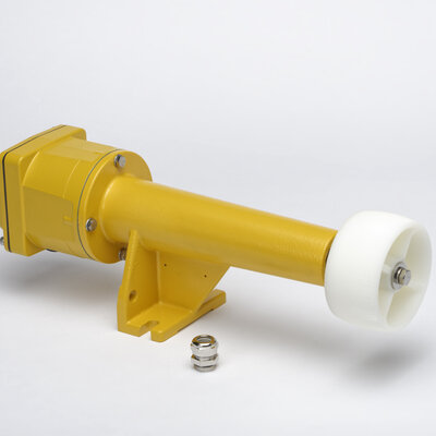
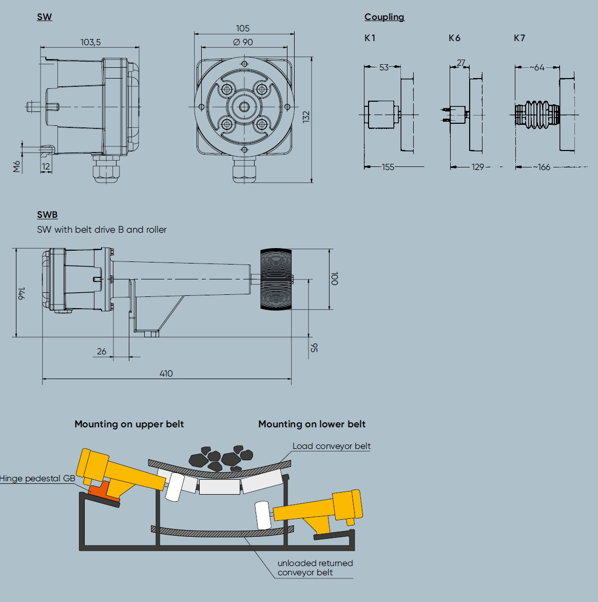
- Standstill monitor SWB with belt drive and roller
- Alu housing
- IP65
Features
Kiepe standstill monitors are used to monitor transport and conveyor systems of all kinds, such as elevators and conveyor belts, fans, mills as well as fabric, wire, foil or paper tears in AC circuits. The devices are also installed as brake monitors on presses, transfer line drives, balancing machines and centrifuges. On mixing machines and drives, the standstill monitors take on the function of direction of rotation monitors.
Corrosive
- Powder
- Conditionally Suitable
- Gravel
- Conditionally Suitable
- Rubble
- Conditionally Suitable
Non-Corrosive
- Powder
- Suitable
- Gravel
- Suitable
- Rubble
- Not Suitable
Kiepe SWB standstill monitors are electromechanical devices that do not require a power supply. The drive shaft [1] drives the hermetically sealed fluid coupling [4] [5] via the magnetic coupling [2] [3] . This actuates the respective contact spring set [6] for clockwise or anticlockwise rotation. As the drive speed increases, so does the torque generated in the fluid coupling. If the torque is greater than the counteracting preload force of the factory-set contact springs, the contact is switched over. A further increase in the drive speed increases the contact pressure only slightly, as the torque of the fluid coupling is stabilized by the slip of the magnetic coupling. If the speed drops, the contact switches back when the preload of the contact springs becomes greater than the torque generated by the drive speed. The switching point setting of the standstill monitor is determined by the viscosity of the oil in the fluid coupling and by the pretension of the contact spring sets. The set switching speeds have a tolerance of +/- 30% depending on the ambient temperature and the operating temperature. Contact is made gradually. The operating speed must therefore be higher than the switching speed to ensure contact reliability. Due to their design, standstill monitors with very low switching points have an advantageous switching delay of approx. 2 seconds. The standstill monitors are single-mechanical devices. They must be protected by suitable design measures. If speeds greater than 500 rpm are to be monitored, the use of our electronic speed monitors is recommended.
| Designation | Speed monitoring standstill monitor SWB |
|---|---|
| Type of actuation | Electromechanical via magnetic-oil coupling |
| Complies with | DIN EN 60204-1, DIN EN 60947-1, DIN EN 60947-5-1 |
| Suitable for | Control circuits (230V) according to DIN EN 60204-1 |
| Enclosure | Aluminium |
|---|---|
| Finish | PU 2K-Paint yellow, RAL 1004 |
| Seal (cover) | EPDM |
| Shaft | -2 S: Round 10mm ; -3S: Flat 9 mm x 2.8 mm |
| Fastening | 4 x M6 |
| Rated speed (max.) | 3000 U/min |
| Weight | 1,3 kg |
| Switching system | 2 SPDT (slow-action contacts) |
|---|---|
Cable entry (included in the scope of delivery) | 1 x M20 x 1,5; seald with 1x red screw plug (1x screwed cable gland; sealing area Ø9 mm to Ø13mm) |
| Utilization category | AC-14: 240V; 0,3A |
| Connection cross section (max.) | 2,5 mm2 |
| Protective conductor connection | Protection class I / protection by protective conductor |
| Rated insulation voltage Ui | 250 V |
| Rated impulse withstand voltage Uimp | 2,5 kV, overvoltage categorie II, degree of soiling 2 |
| Permissible ambient temperature | – 25°C… +70°C |
|---|---|
| Protection rating (according to EN 60529) | IP65 |
Standstill monitors type SWB are attached to the substructure of the monitored machine using 4 M6 screws each. This is done using flange (F1, F2) or fixing foot F4. The connection to the rotating shaft is made using couplings (K1, K6, K7) depending on the SWB shaft version. When the speed is taken directly from the belt, the SWB is attached to the belt drive B. The belt drive is pressed against the cleaned side of the belt using a hinge pedestal GB. The electrical connection is made when the device is open via the cable gland included in the scope of delivery directly to the accessible connection screws (see connection drawing, 1,2,P or 3,4,P) of the potential-free changeover contacts of the SWB.
Note When using the belt drive B, make sure that the belt load cannot damage the SWB. With direct connection using fasteners, care must be taken to ensure that the SWB can resonate with the rotating part of the machine.


Variants
| Name | Ordering No. | Weight | Roller | Switching Points Typical |
|---|---|---|---|---|
| SWB 01-2 S/K | 92.041 137.101 | 4.1 kg / 1 Unit | Plastic | < 3 rpm |
| SWB 02-2 S/K | 92.041 137.102 | 4.1 kg / 1 Unit | Plastic | < 5 rpm |
| SWB 03-2 S/K | 92.041 137.103 | 4.1 kg / 1 Unit | Plastic | < 10 rpm |
| SWB 04-2 S/K | 92.041 137.104 | 4.1 kg / 1 Unit | Plastic | < 70 rpm |
| SWB 05-2 S/K | 92.041 137.105 | 4.1 kg / 1 Unit | Plastic | < 150 rpm |
Downloads
You have a question? We are here for you!
We are looking forward to hearing from you. We are happy to advise you and help you with the selection of the right product.